Potions Cabinets
 Redesigned in 2019. Scroll toward the bottom of the page for updates.
The potions cabinets were the crown jewels of the party.
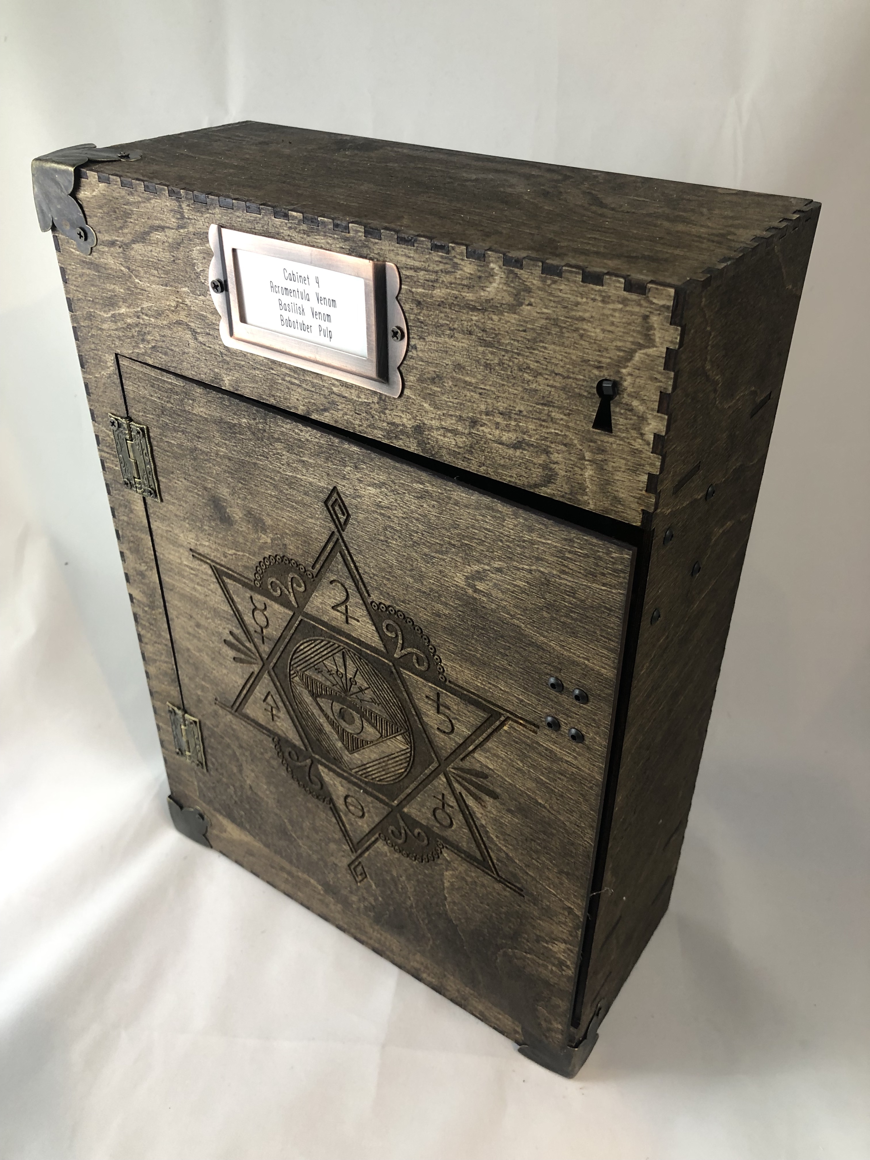
They were where the theming of the Potions Textbook dovetailed with the immersion of using your wand to start building your own drinks. My goal was to make them a combination of beautiful woodworking and a functional electronics package. I feel that I hit that goal, but I’ll let you be the judge.
You can find the final list of parts, laser files, and embedded source code on the GitHub cabinets page. Do note that the current incarnation of the potions textbook requires four cabinets, so multiply your bill of materials, time, and cost accordingly.
You can see a quick demo of one in action — activated by sensing the presence of a wand — in this video:
My rough prototype used a full-sized Arduino, a Hall effects transistor (to detect magnets), a servo motor (to, in theory, unlock the cabinet), and a layered+masked Neopixel LED strip. The final design was fairly close to the prototype.
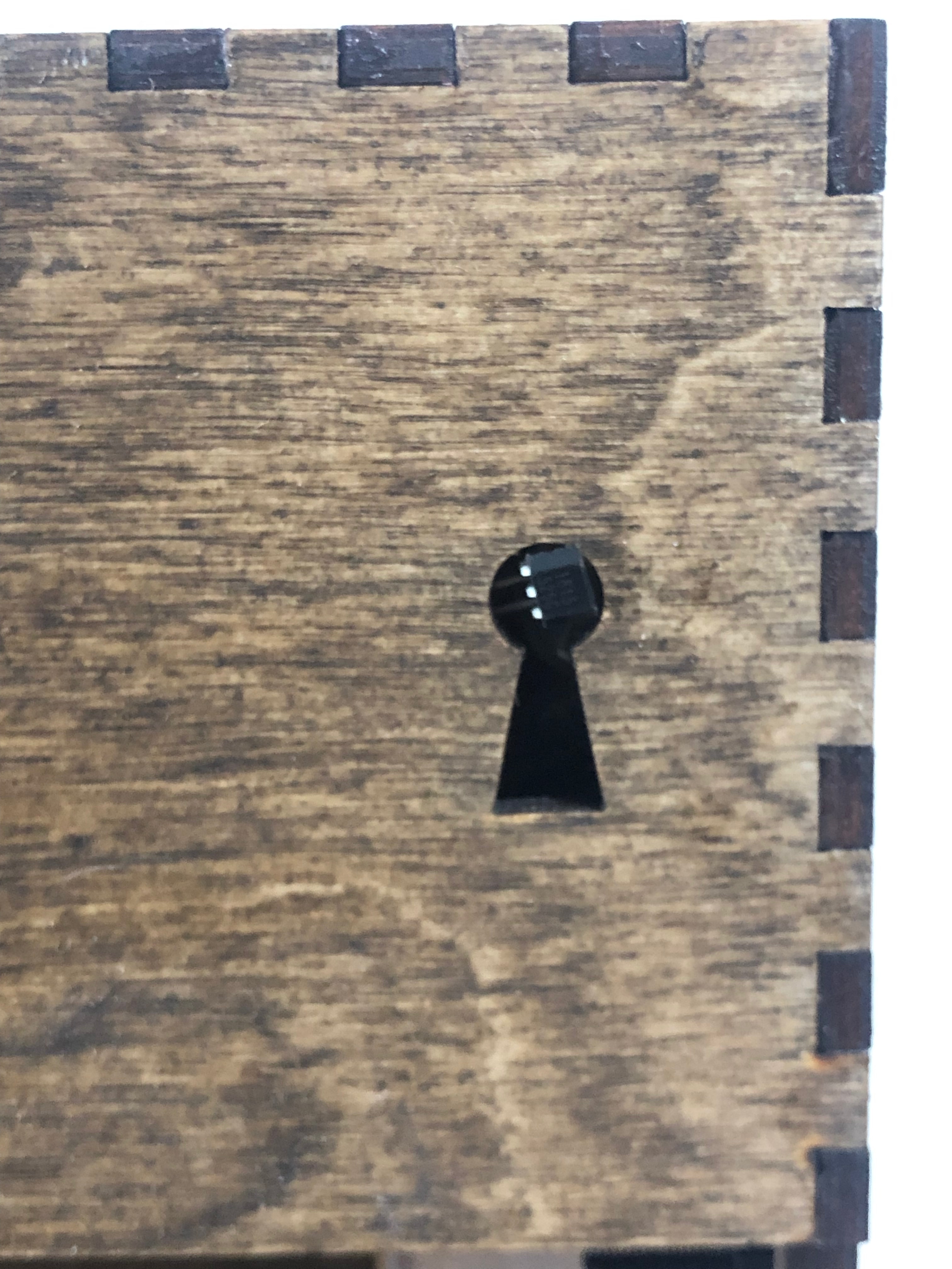
I loved the concept of the secret keyhole image behind the acrylic, but I ultimately needed a real keyhole to make it look like the user was picking the lock with an Alohamora spell. The acrylic didn’t match the carpentry of the cabinets, so I had to drop it. I later used the secret acrylic masking in the [mixing stations[(/classroom/mixing/). I also switched to a solenoid, which much more power behind it, for the unlock mechanism. To save space and cost, I used a $10 Arduino Pro Mini as the microcontroller for the cabinets.
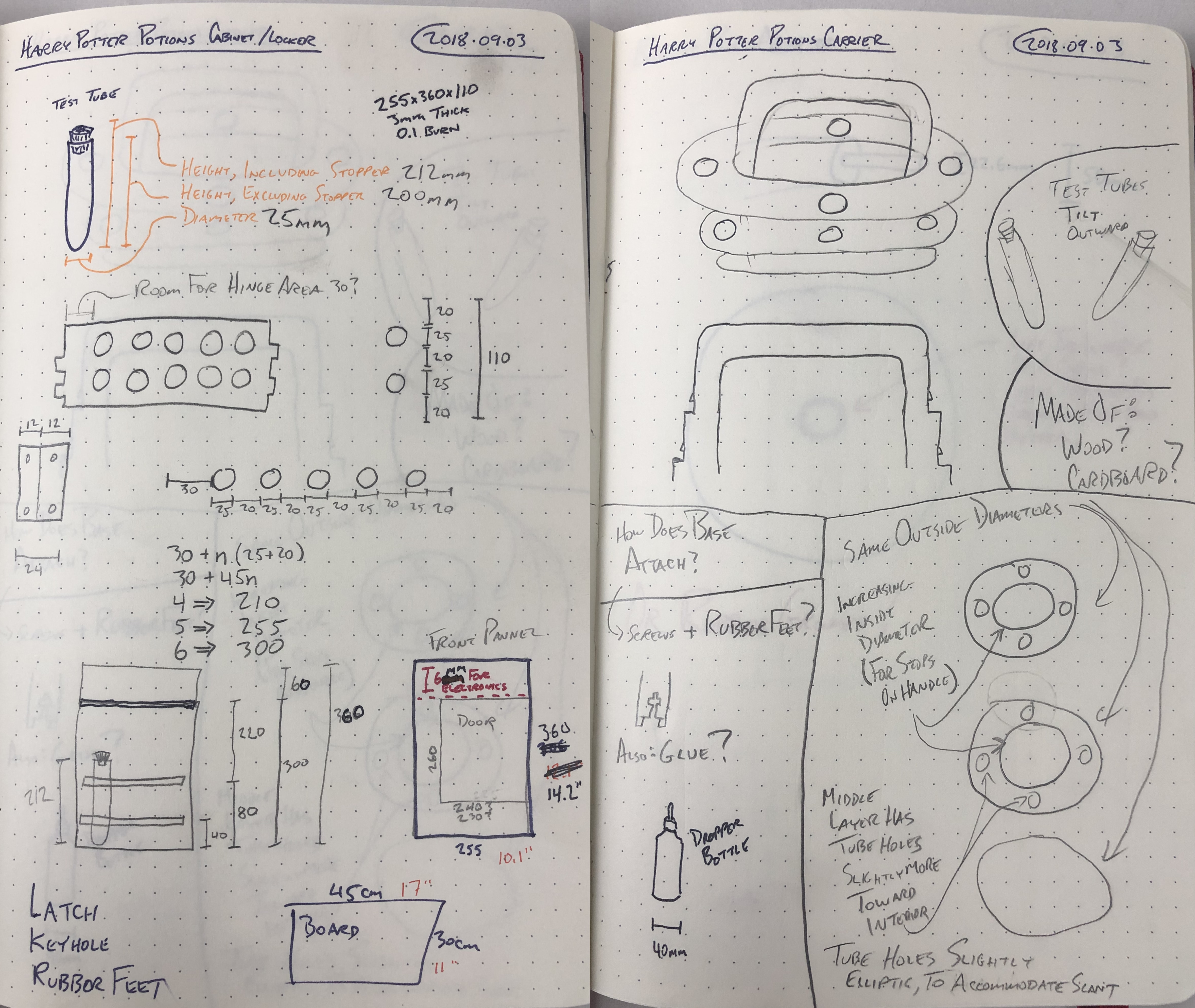
But first, it started with some test tubes. Most standard labware test tubes are fairly small. It took a little bit of imperial-to-metric calculation to find some that could take a 2oz pour — the target maximum quantity I decided I needed for an ingredient.
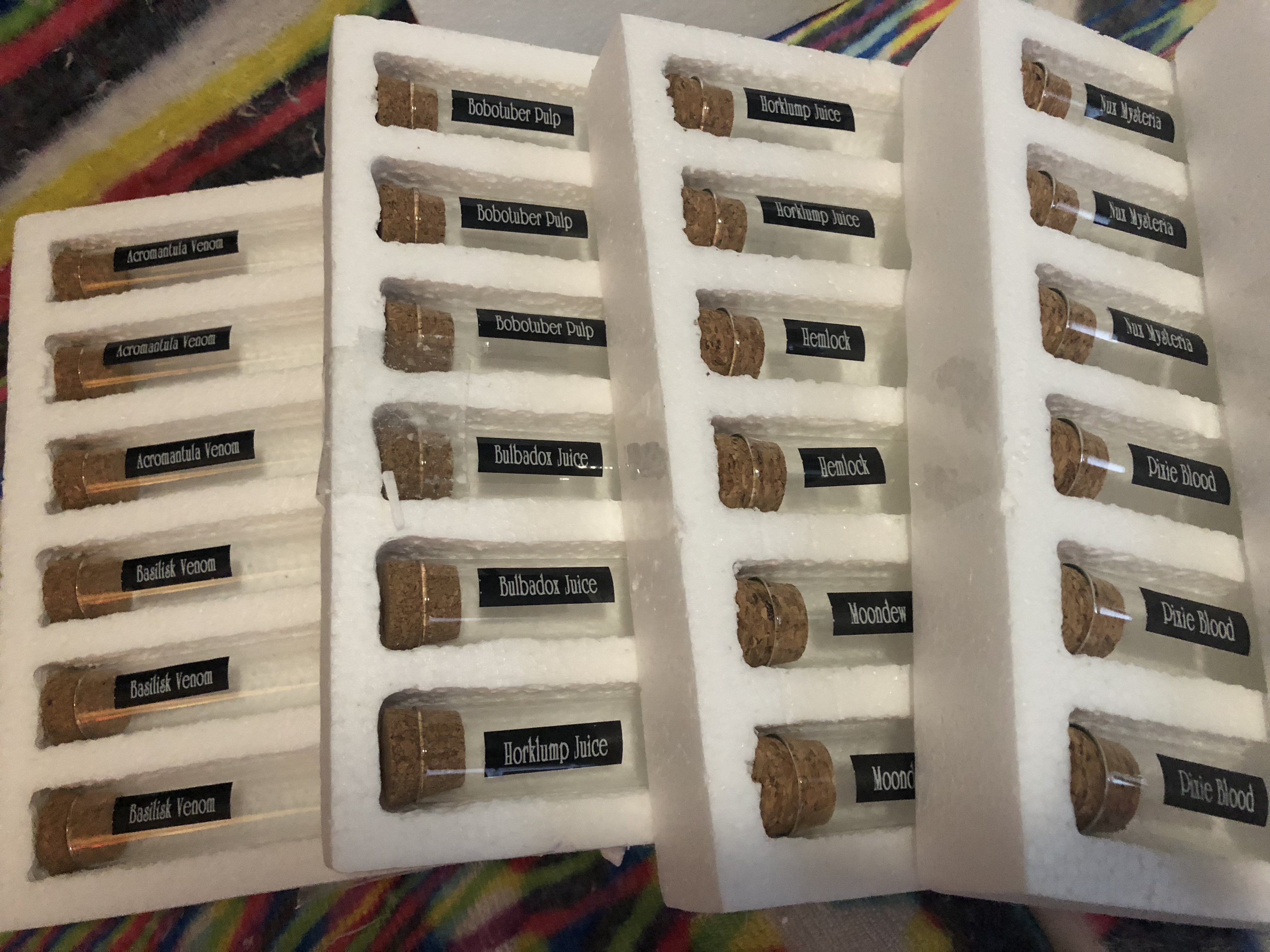
As you can see, the test tube size also informed the size and design of the carriers. A combination of test tube size and laser cutter bed size then informed the size of the cabinets.
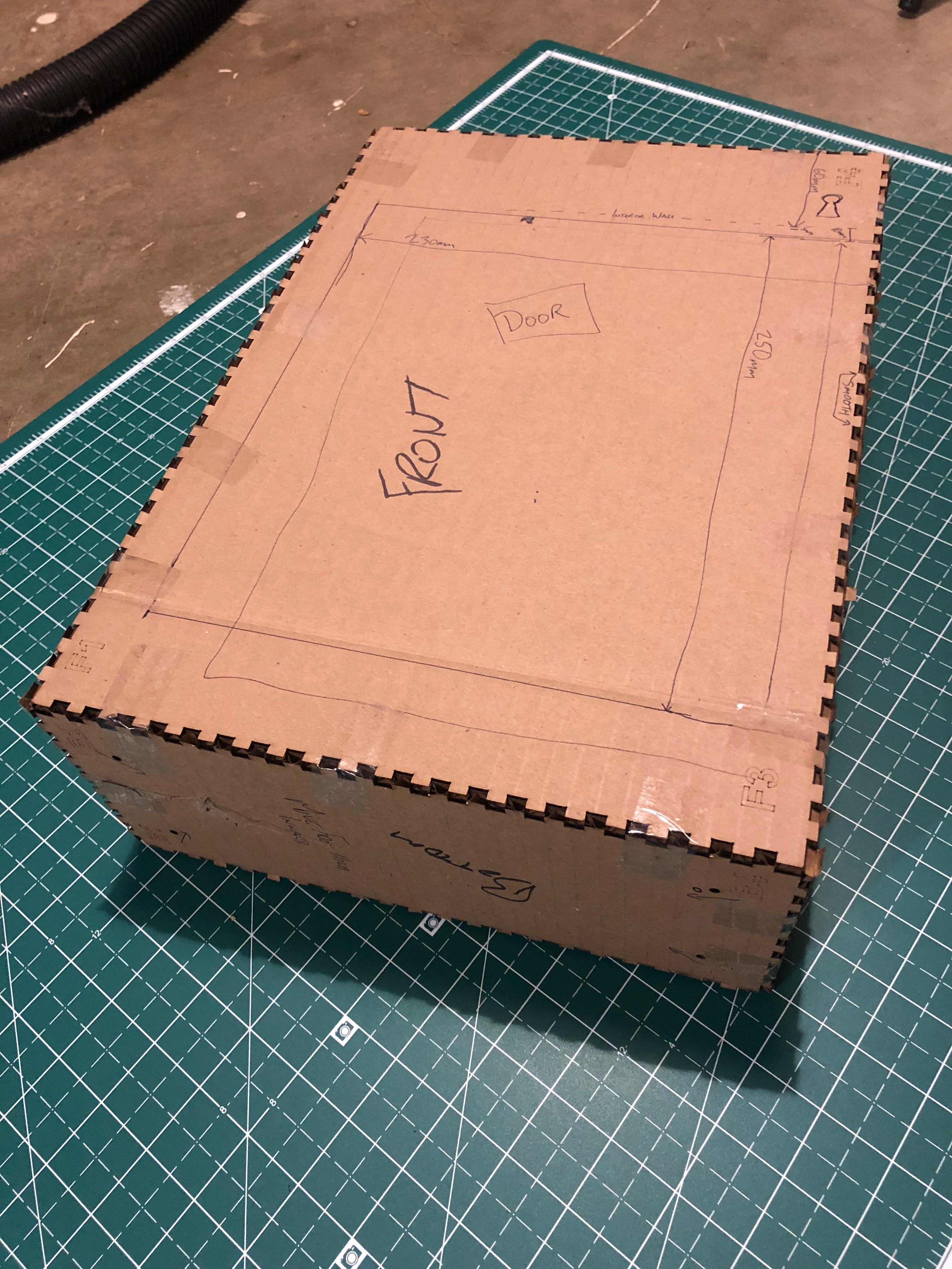
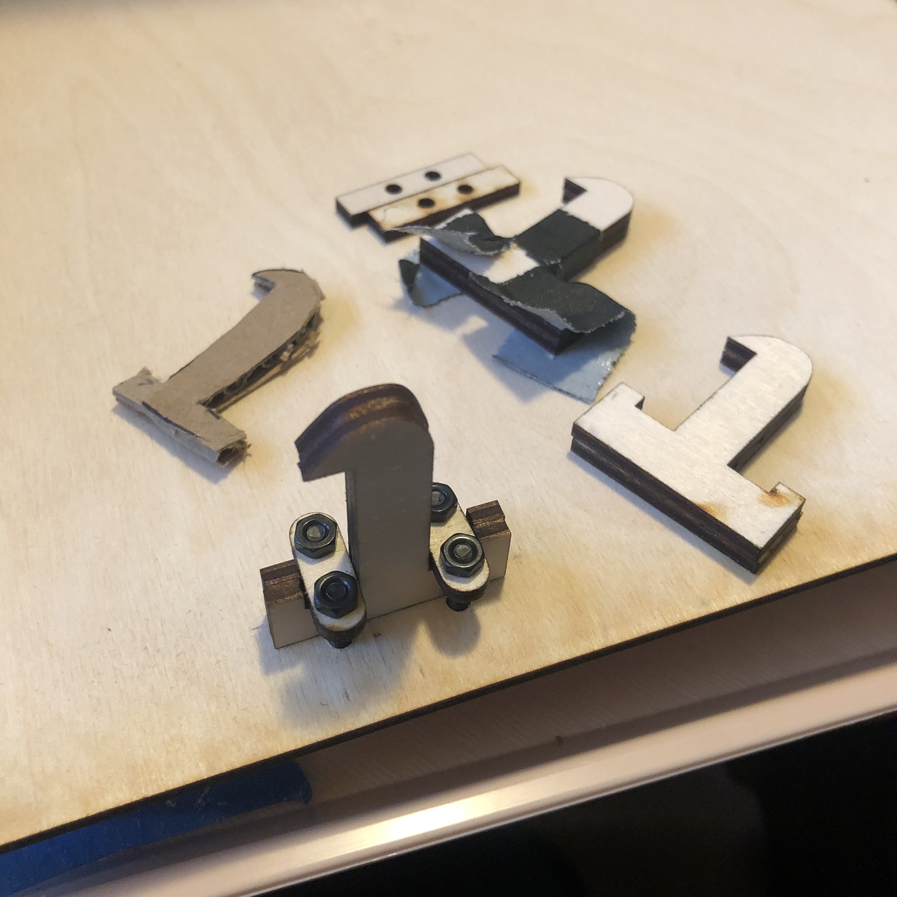
It took several cardboard prototypes on the Glowforge to get the design right. This first one was just some overall dimensions. I had some ideas for how big to make the door, keyhole, and electronics compartment, but this gave me a good physical mockup to scribble on with a marker. Those that are observant will see small etched registration marks (such as F1, F2, F3, and F4 on the front panel). Those let me ensure I have the orientation correct, when designing, assembling, and further revising the design with marked up cardboard.
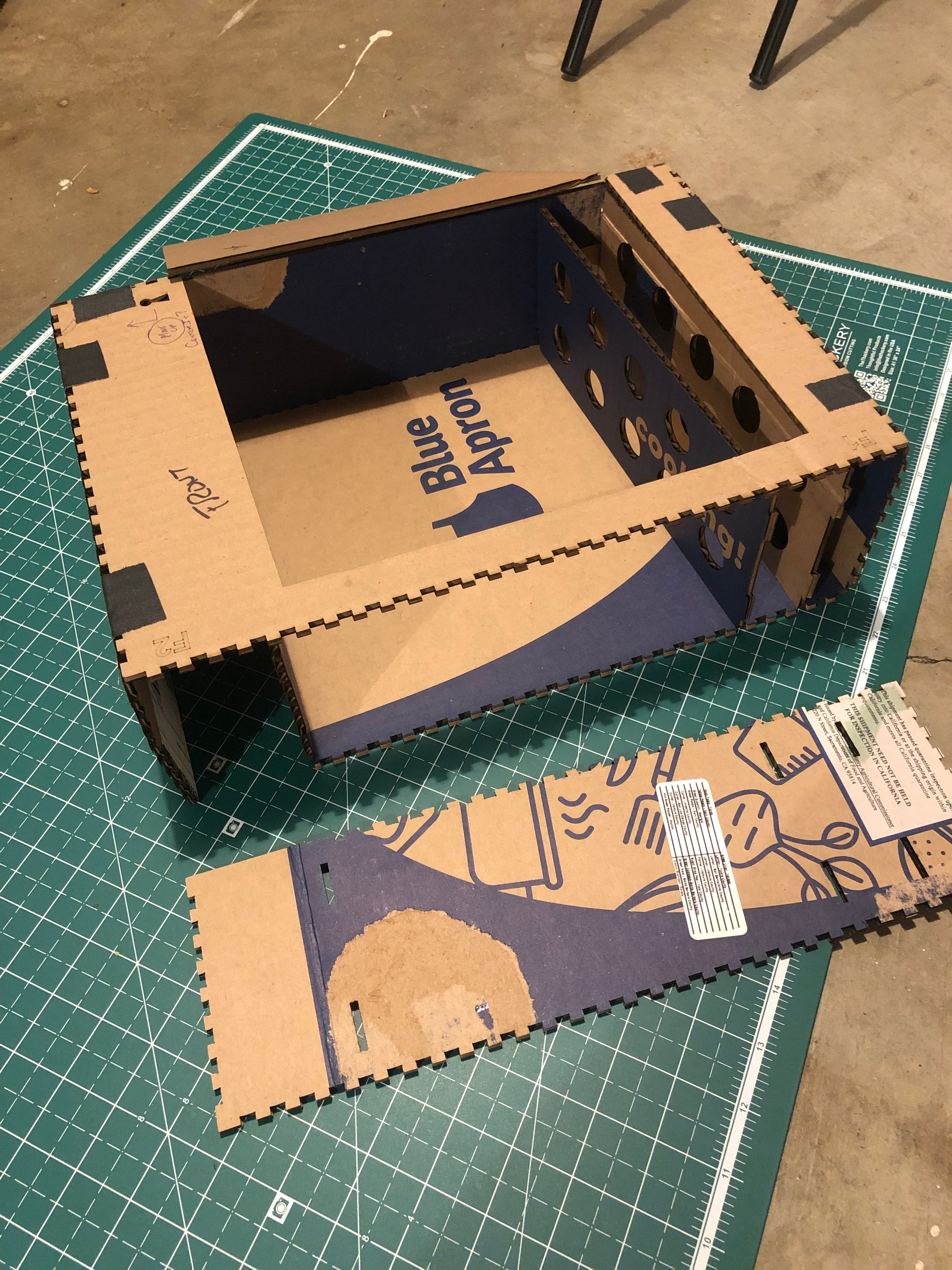
The second prototype included a cut door and internal partitions (for the electronics bay and the test tube rack).
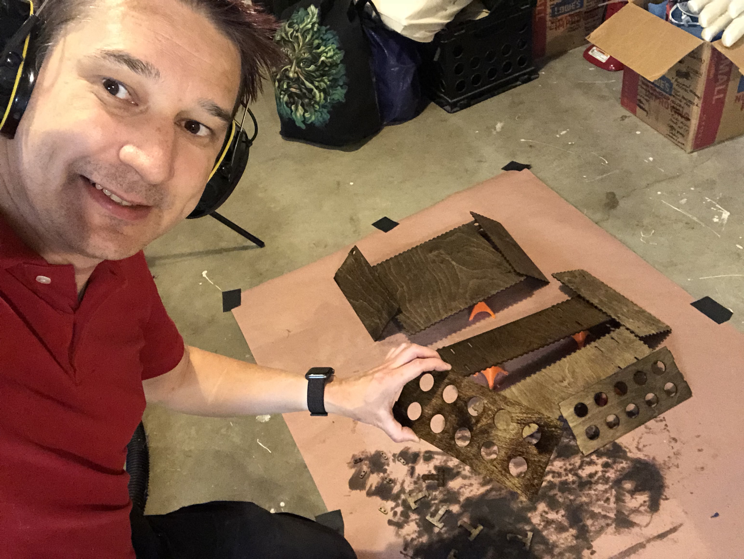
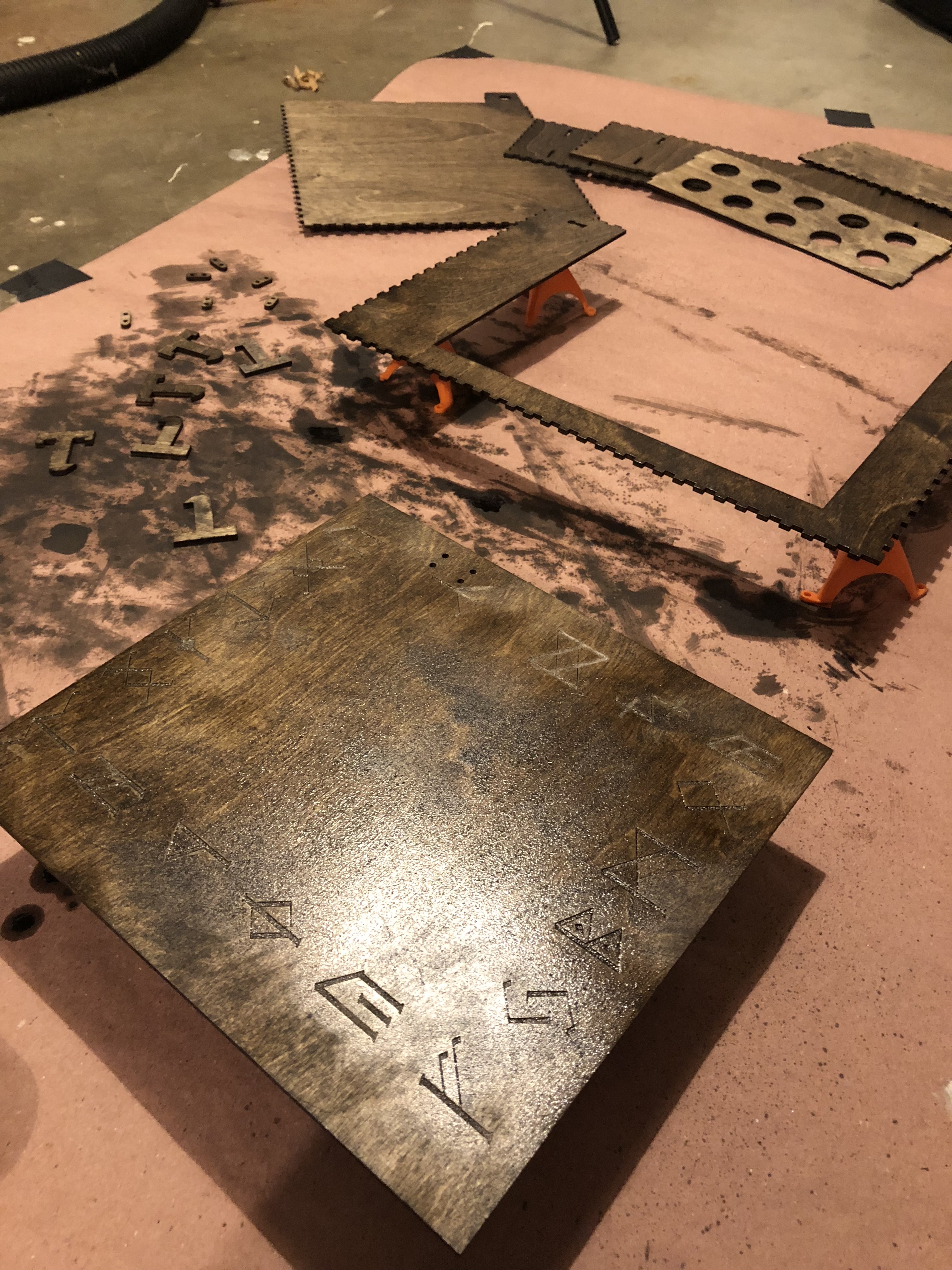
The next step was to take the design and cut it into wood.
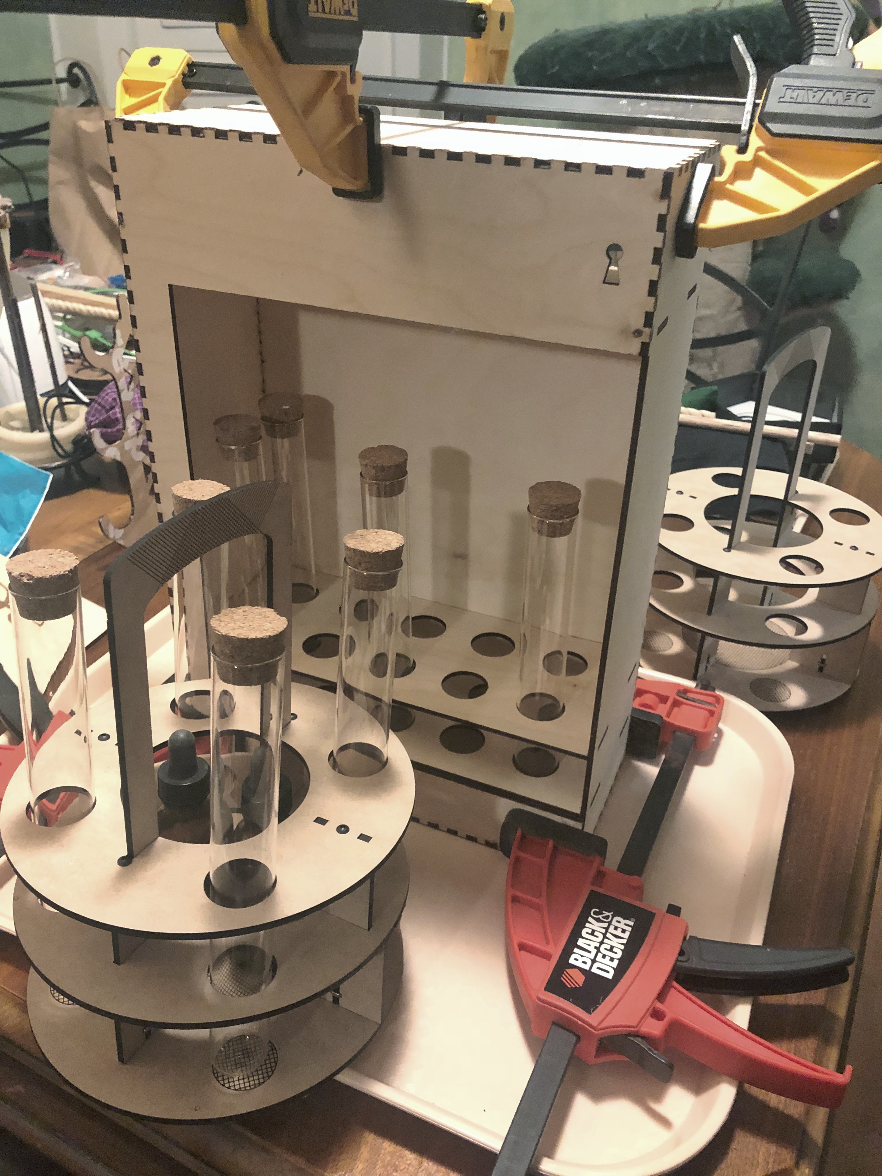
I ended up cutting a little support jig so to help hold the door in place while I attached the brass hinges.
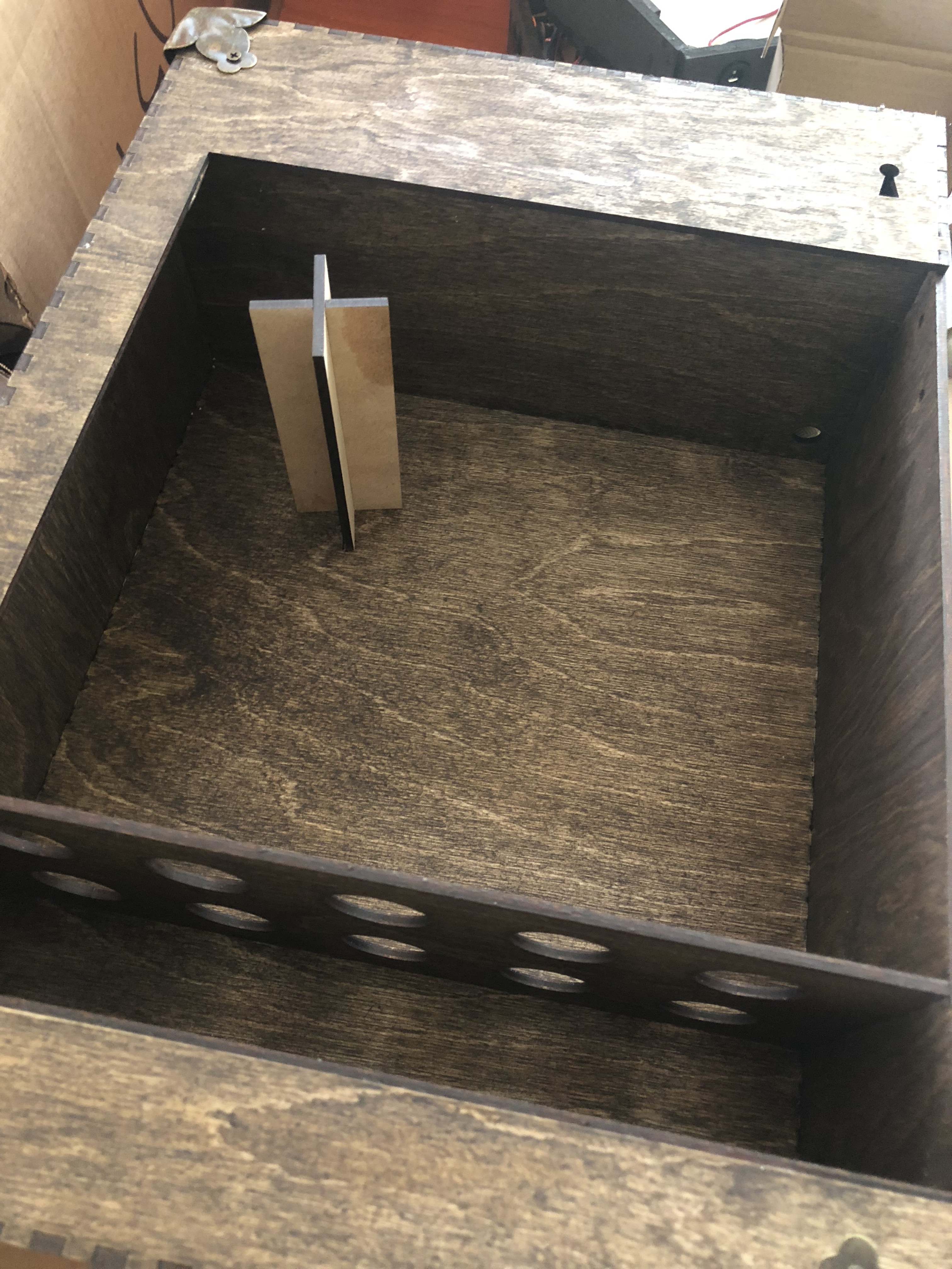
The hollow bay in the back (at the top, behind the keyhole) is quick access to the electronics that control the cabinet.
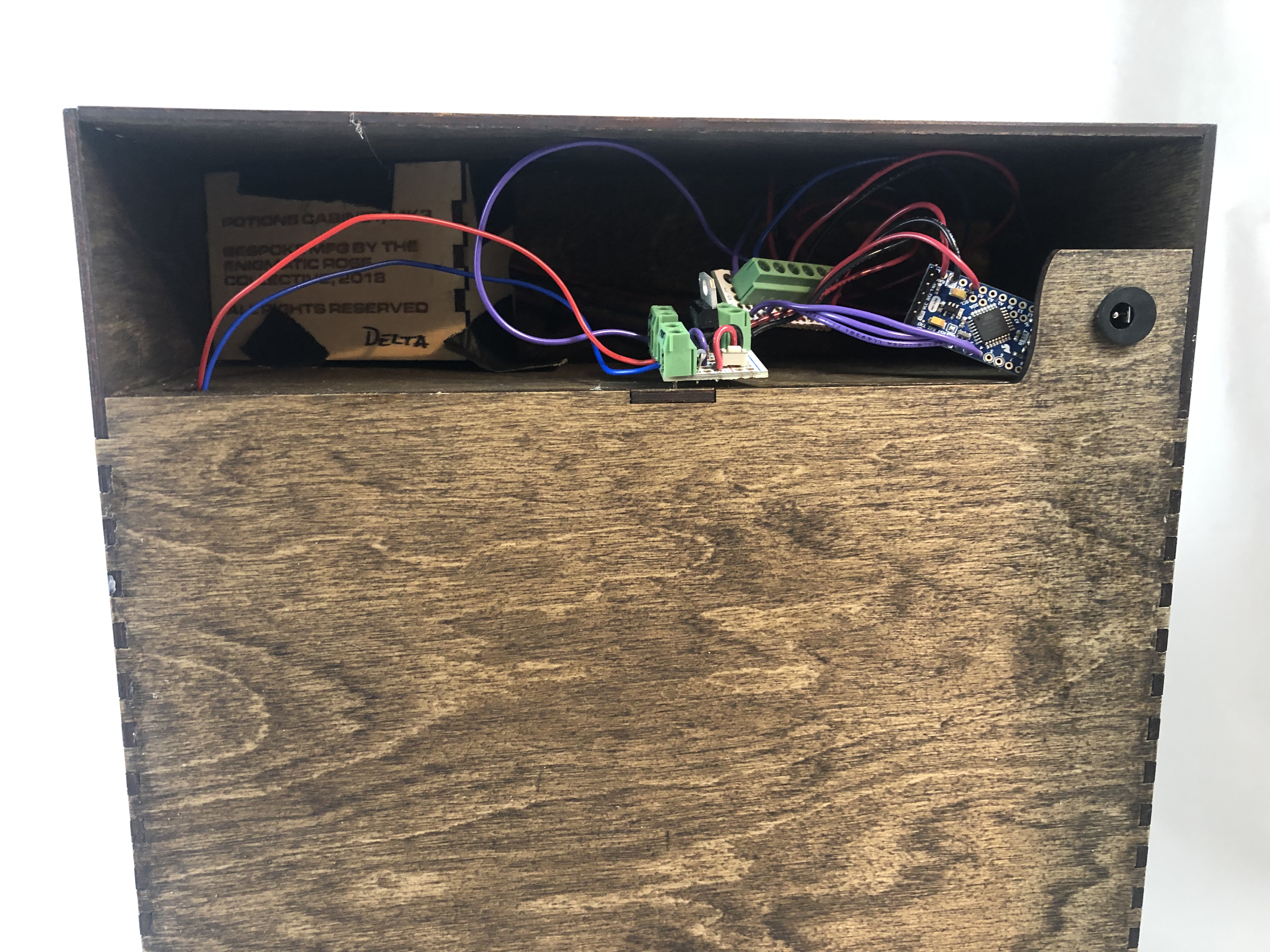
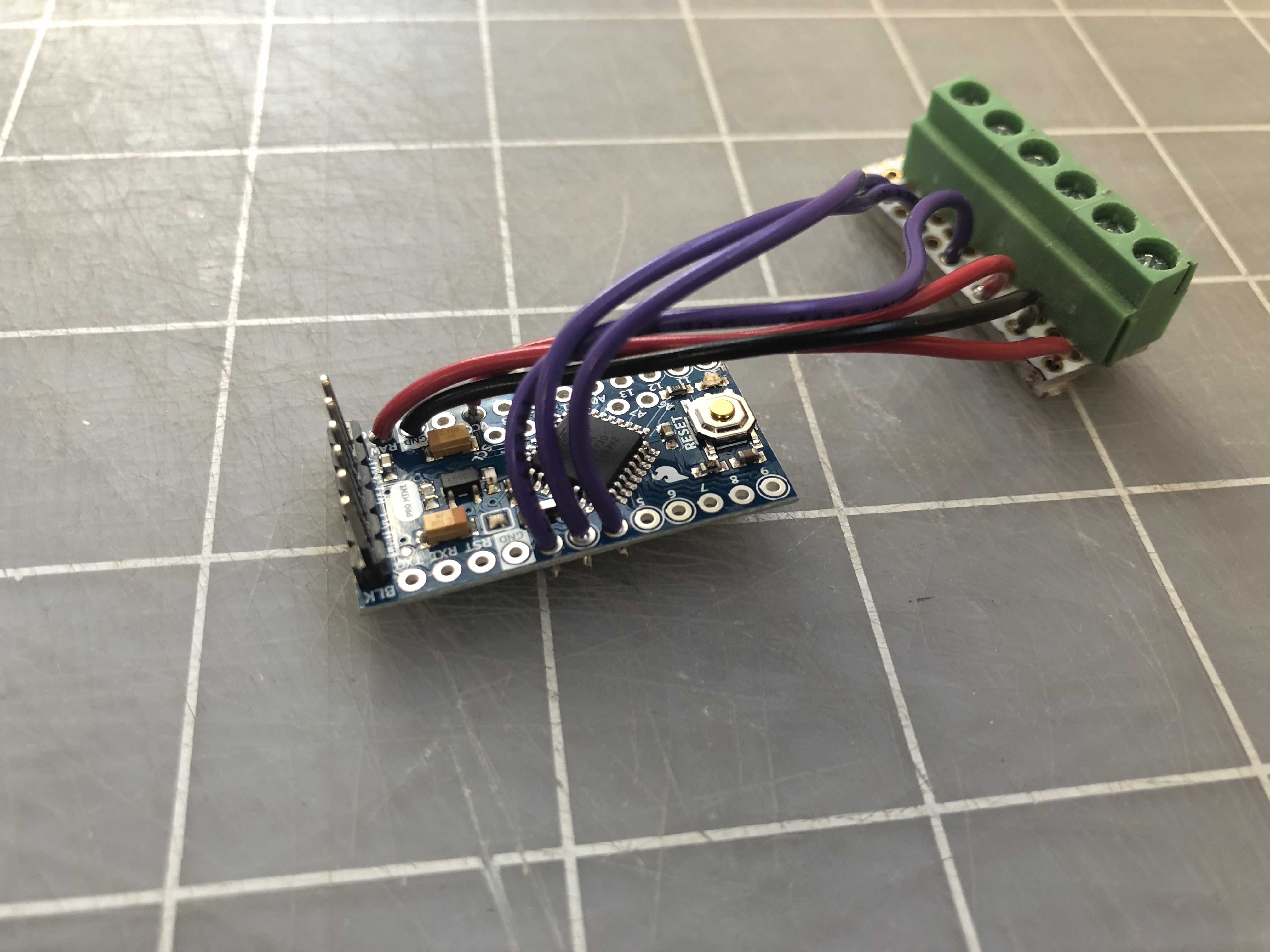
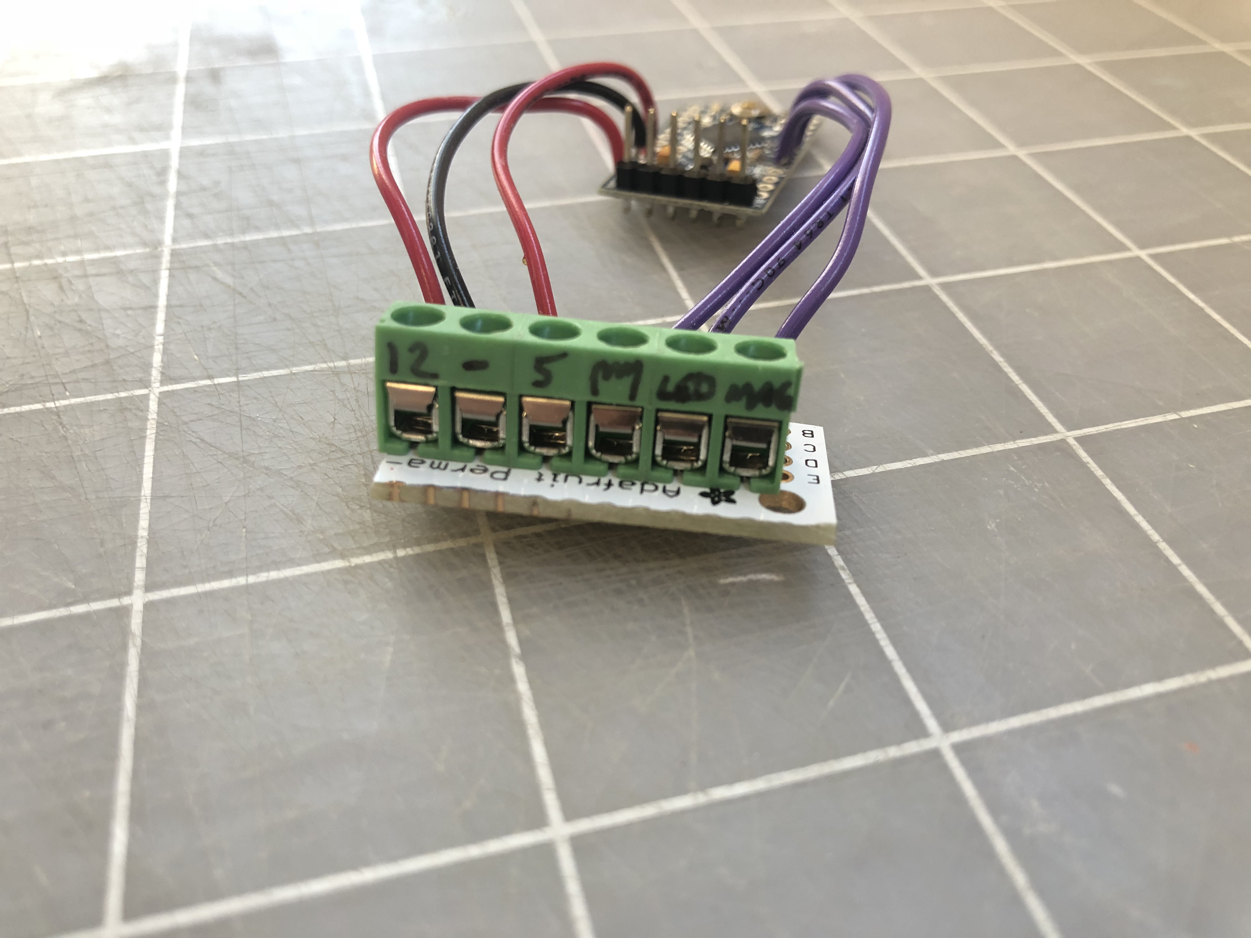
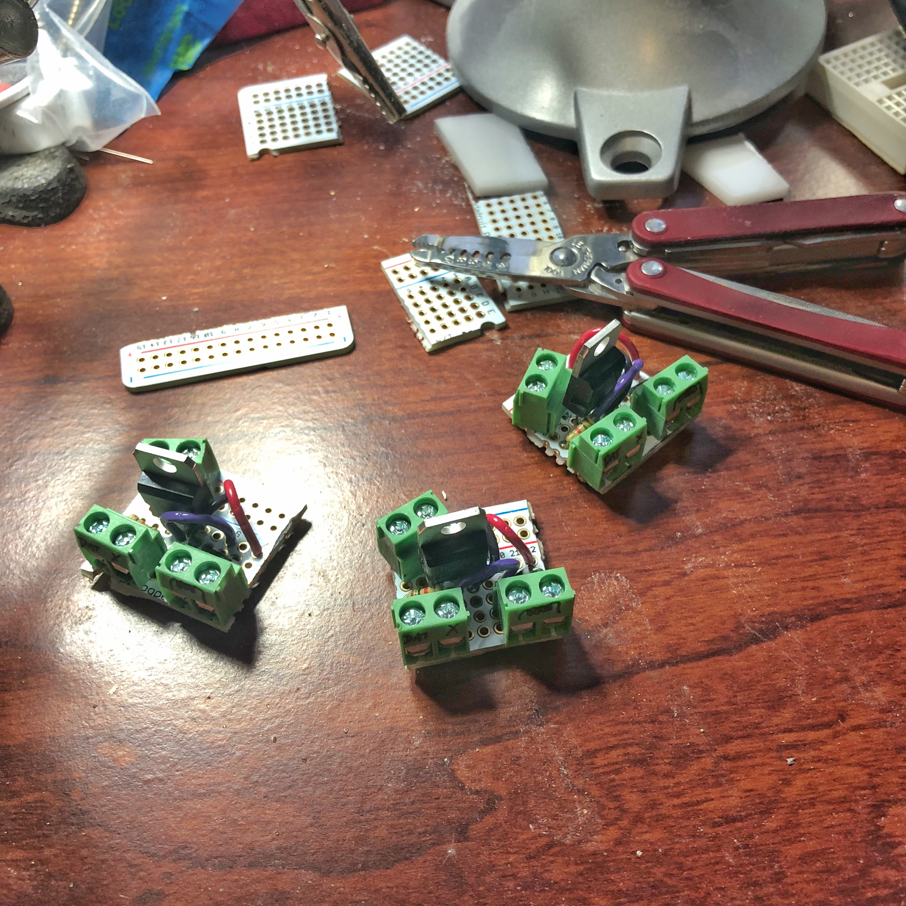
There are four main elements to the electronics package: the Arduino, the magnetic sensor, the solenoid controller, and the LED lights. To keep things both simple and modular, I decided to use small terminal blocks to interconnect the components. The pin spacing on the Arduino Pro Mini is a little too tight to put them on there directly, so I used a small breakout board.
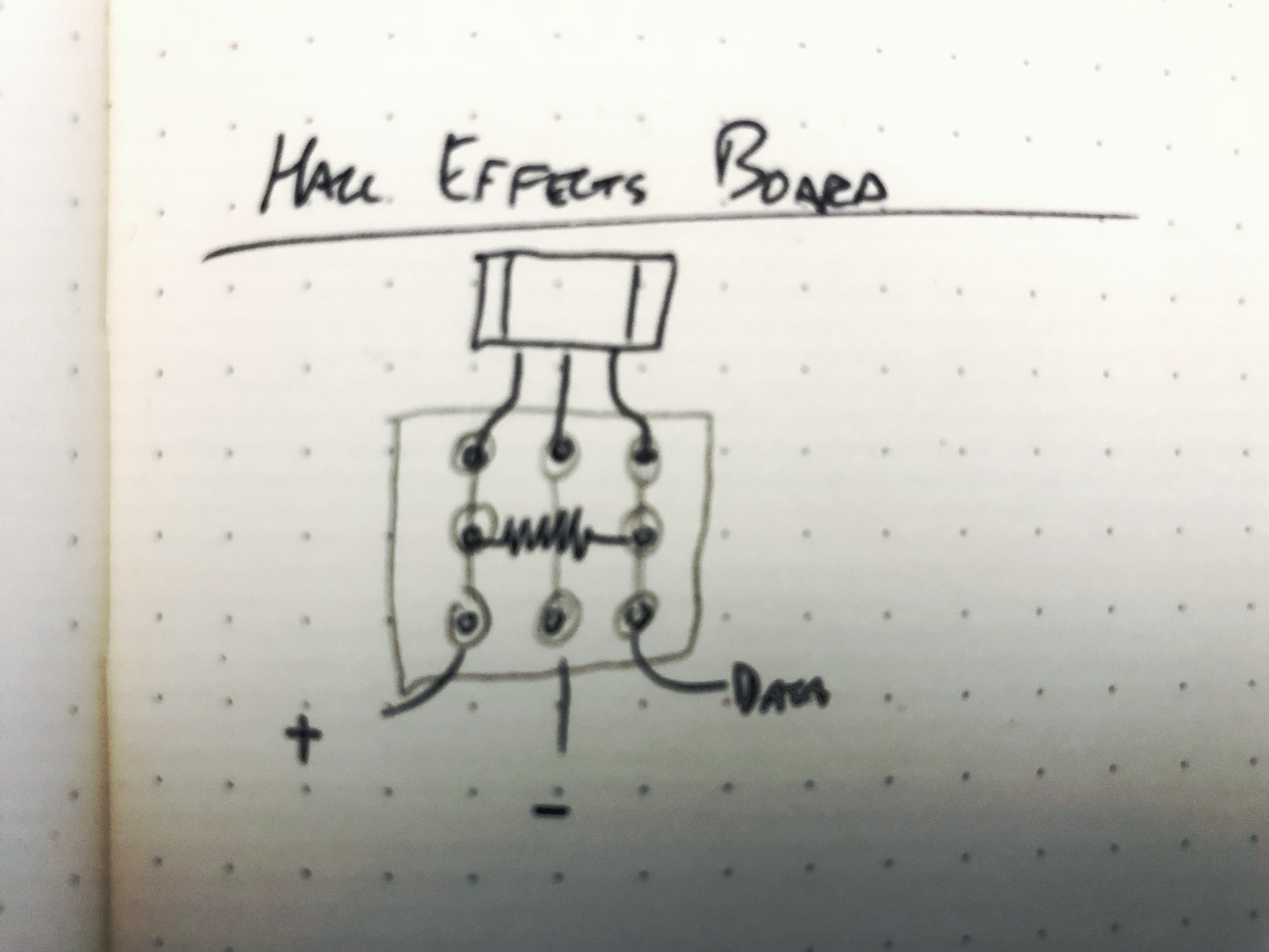
The Hall effects board is extremely simple and simply holds the small magnet-sensing transistor, and can be hot-glued to hold the sensor at the keyhole.
The backside of that keyhole is a short string of RGB LED lights, protected by a light-baffle so that the illumination only shines out the keyhole, not out the (open) back of the electronics bay.
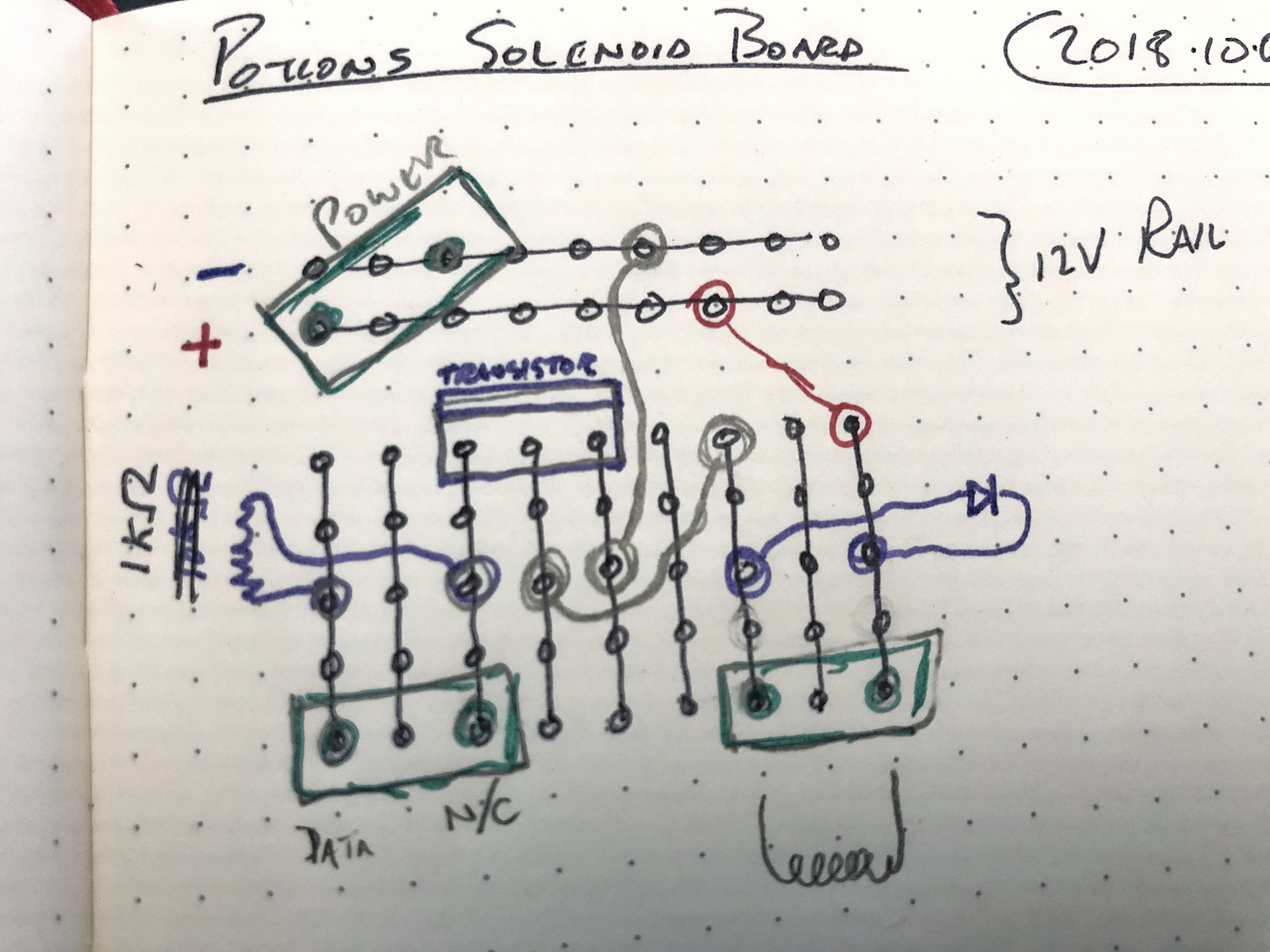
The solenoid controller took the most manual work. They switch the raw 12V of the solenoids by using the 5V logic of the Arduino Pro Mini. Not pictured: I later hacked on a microswitch (bridging ground to the appropriate pin of the solenoid) so that I could manually trigger the solenoid before the production firmware was fully brought up.
The laser files and source code are available on the GitHub project page.
Overall, they take five sheets of 12” x 20” x ⅛” plywood.
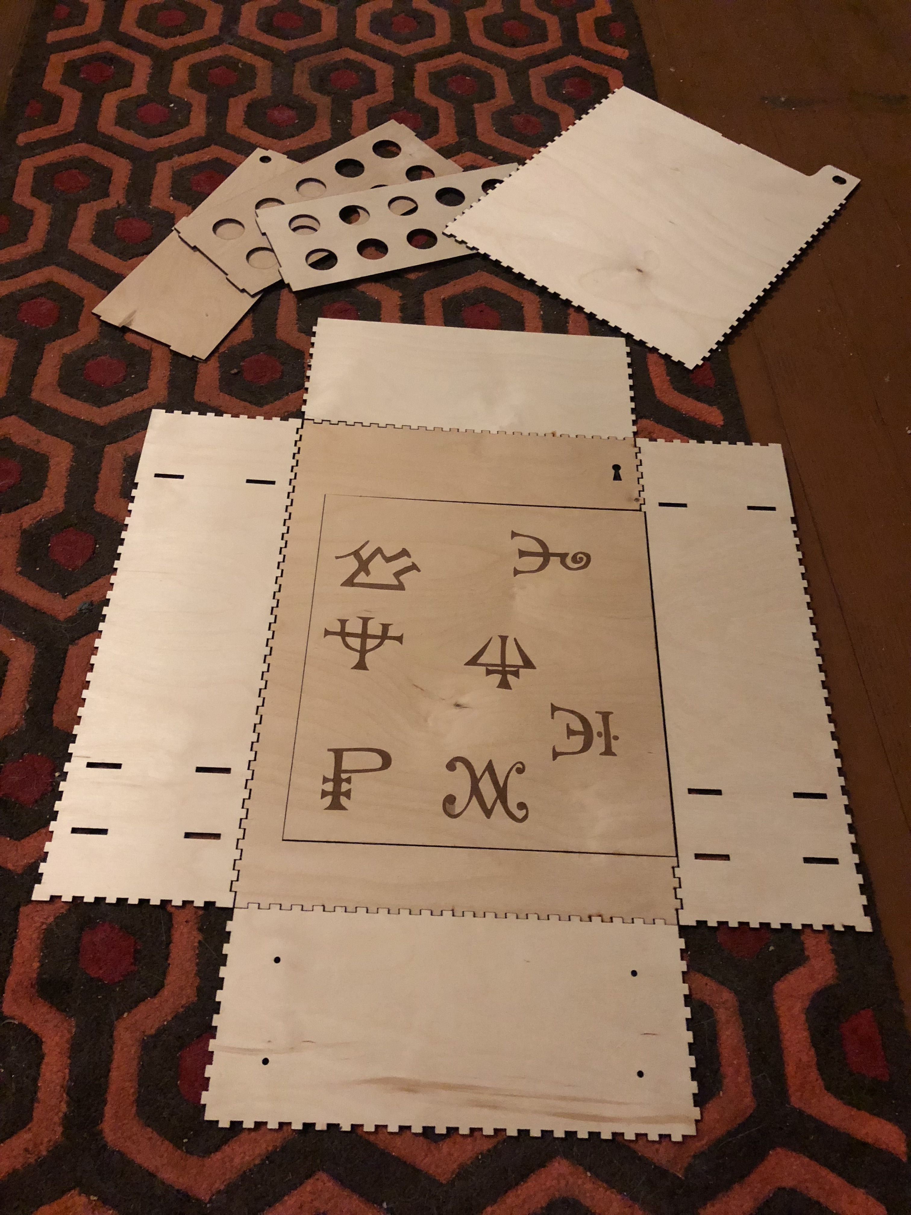
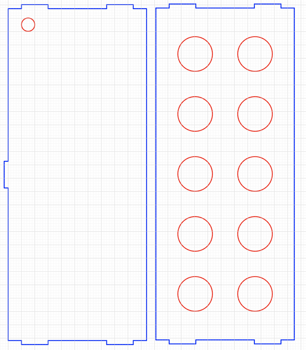
The back, including mount for power jack and opening to access the electronics:
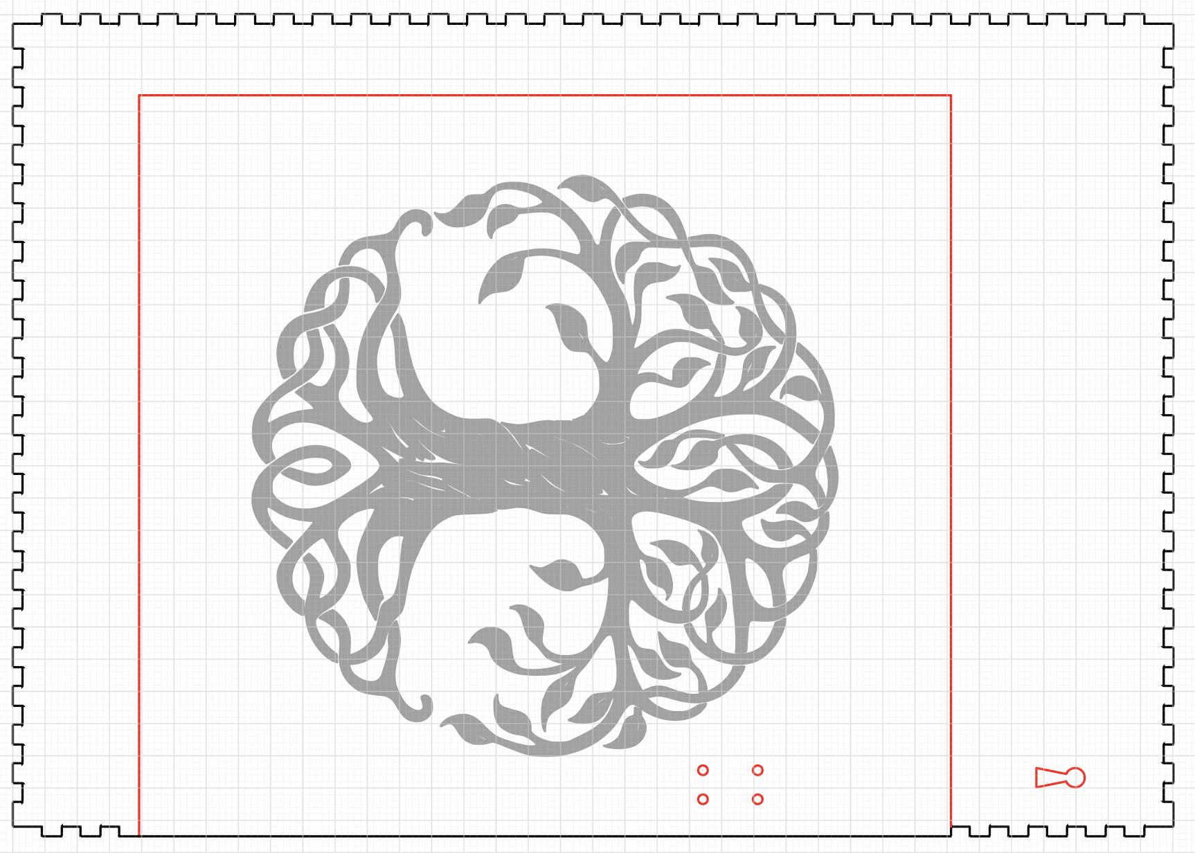
The front:
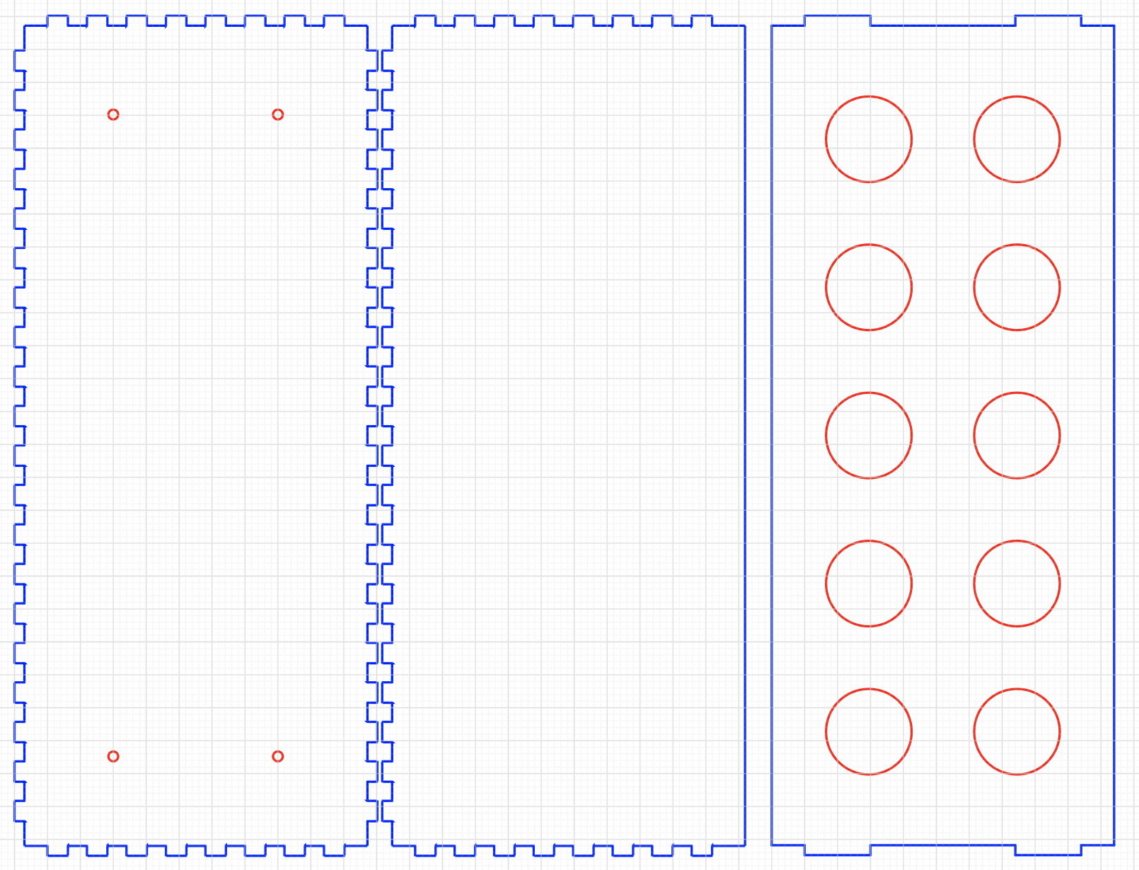
The top of the accessible interior space (with passthrough hole for the solenoid wiring) and one of the test tube carrying layers:
The other test tube carrying layer and the top/bottom exterior panels of the cabinet:
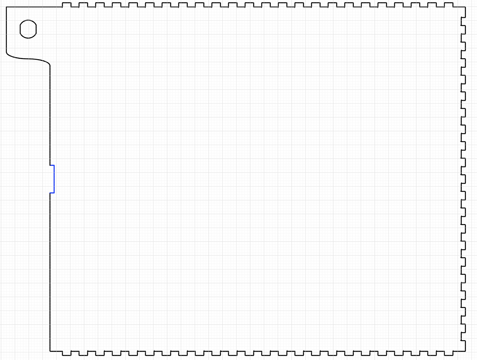
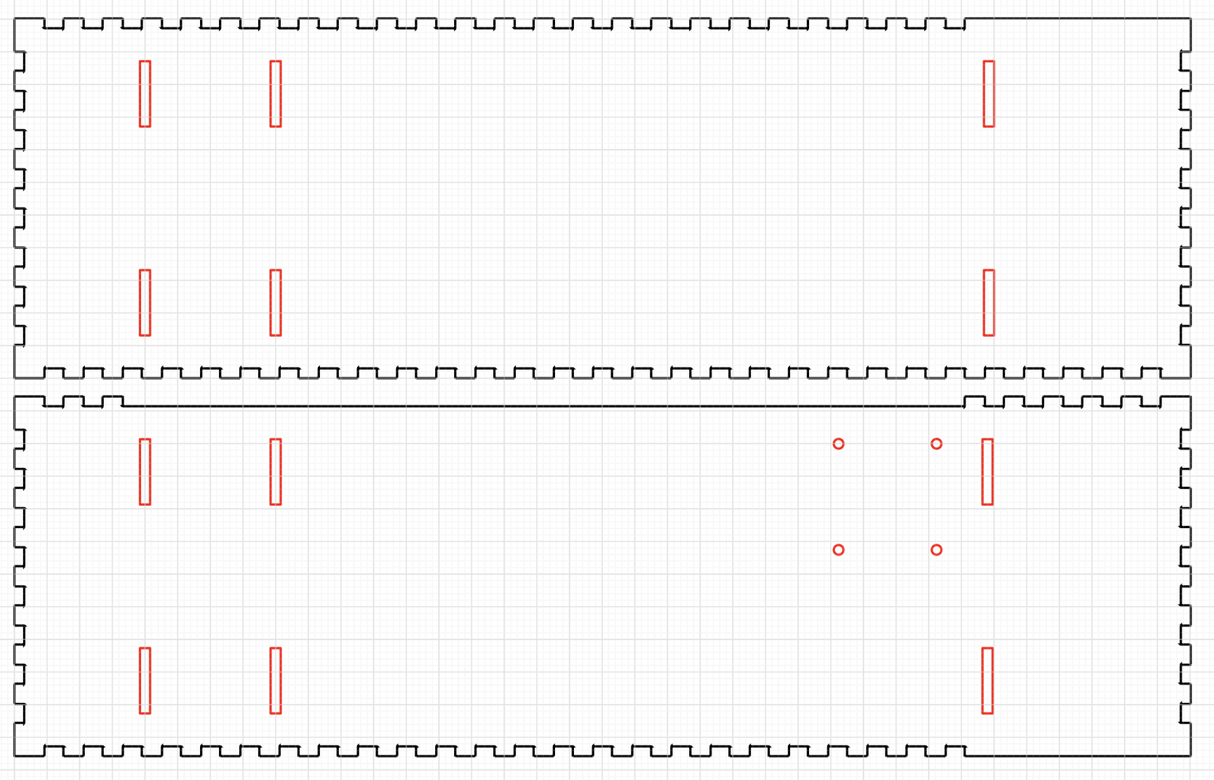
The two sides (one with mounting holes for the solenoid):
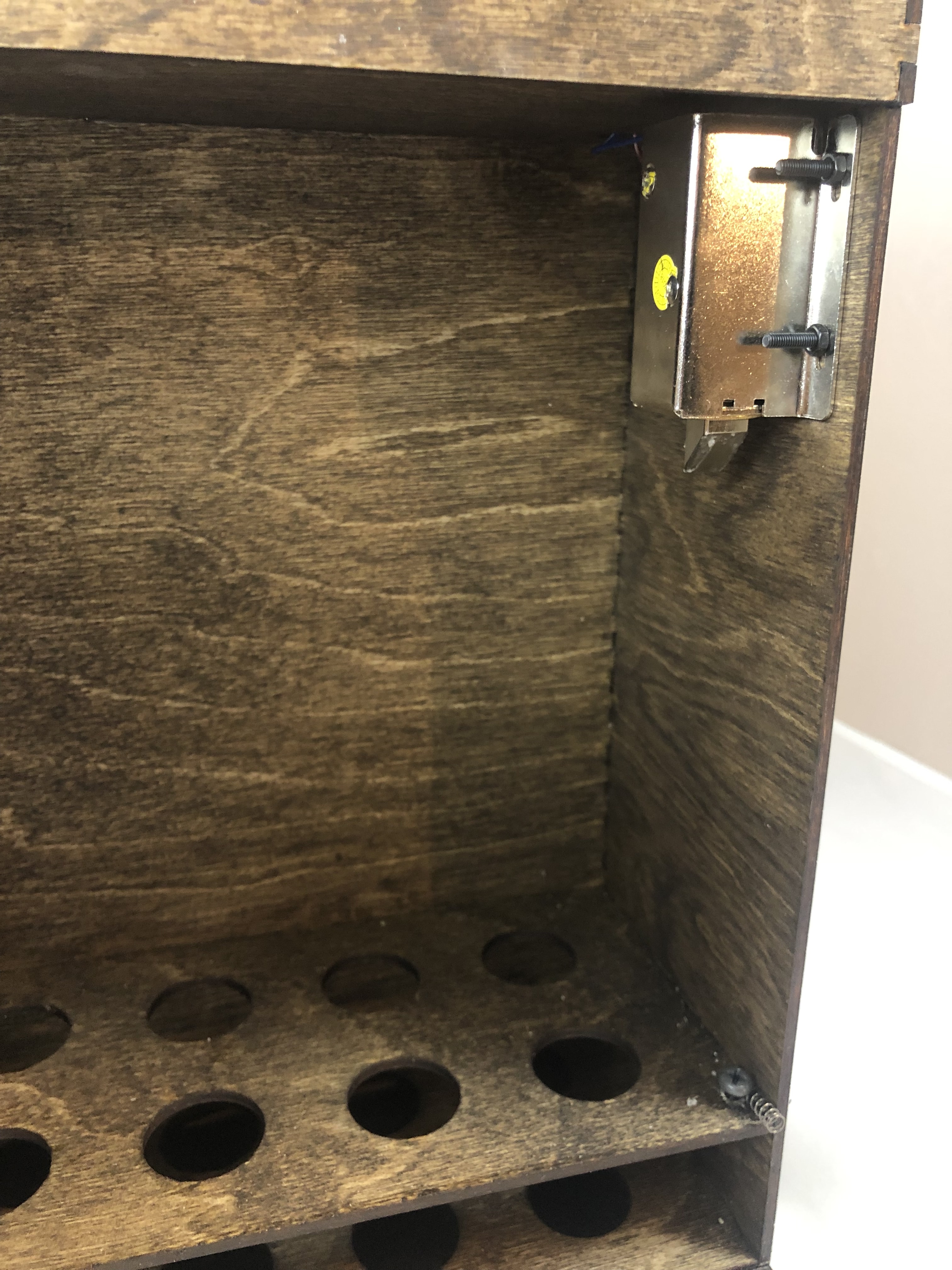
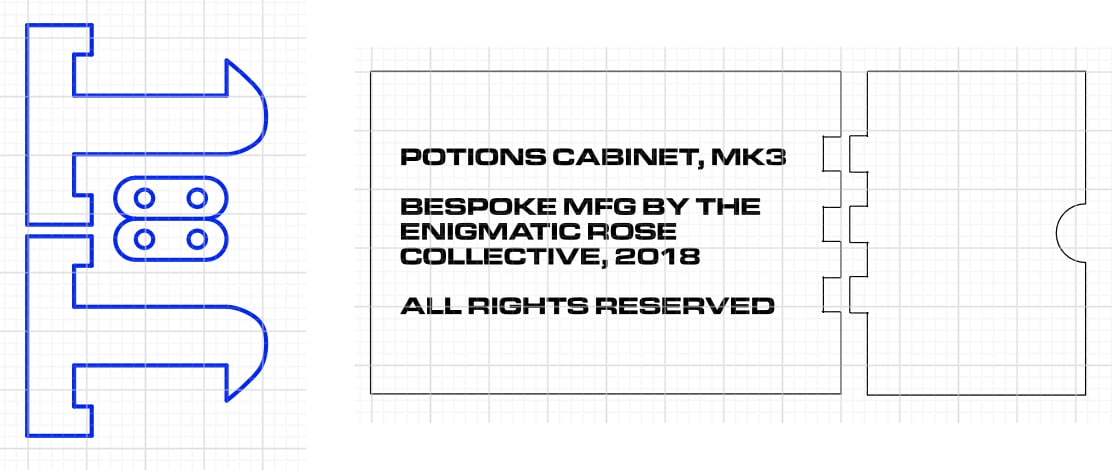
The latch and the light baffle that sits inside the electronics area so that the keyhole LED animation doesn’t splay out onto the wall behind the cabinet:
Redesigned in 2019.
The original run of the party was “blind.” There was no user or user-experience testing. This uncovered a minor flaw in operating the cabinets. When activated with a wand, the end of the want can potentially obscure the light glowing from the keyhole — which led to a little bit of confusion about whether or not it worked correctly. We also found that in the dim light of the kitchen, it was difficult to read the test tube labels.
For the 2019 run of the party, I figured that having a little magical-chime sound effect, similar to the Tinkerbell “turn the page” sound in old Disney audio+physical kids books, would help with the “did it work?” problem. A dimmable light strip would help with visibility (and is also another, visual, indicator that it worked). I used the same RGB-addressible LEDs for the inside that I used for the keyhole. And I found a great little breakout board, around the VS1000 Vorbis Player chip, that lets you preload a WAV file into Flash, with playback triggered by yanking on a GPIO pin. Each also needed a small speaker.
So for party 2019, I hacked together yet another daughterboard to add these features. I also discovered in the process of adding these components that I was stressing the Arduino’s voltage regulator a bit too much, so added a separate one directly off the 12V solenoid line to power all the existing and new 5V accessories: keyhole light, internal visibility light, and audio chip.
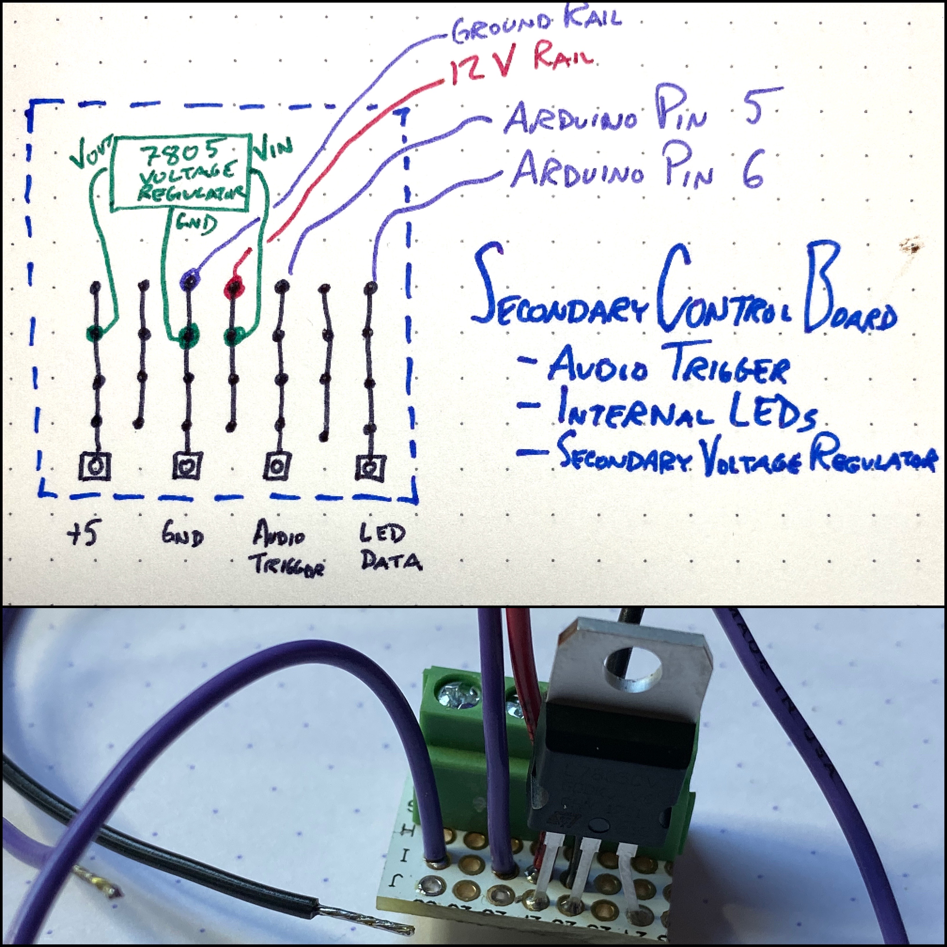
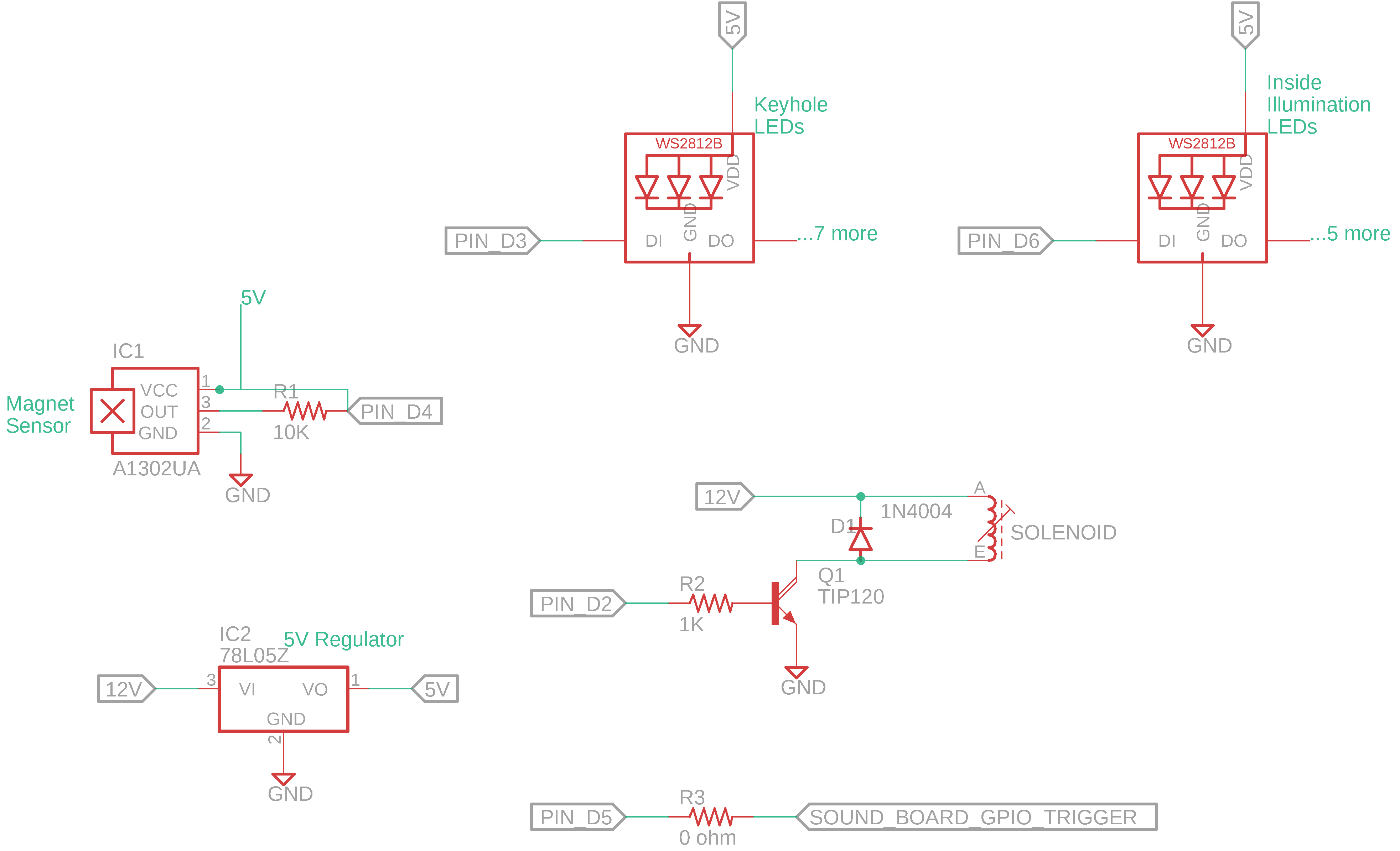
The final schematic looks a bit like this: